Quick links:
In most CAD programs, blocks are used as named groups of geometric objects that represent a single 2D or 3D entity. They are helpful to repeat content, such as symbols, standard building components, and other details.
While most CAD users are familiar with Dynamic Blocks in AutoCAD®, this article explores Parametric Blocks in BricsCAD. See how to create and modify them, learn the benefits, and learn how they differ from Dynamic Blocks in AutoCAD. Discover why BricsCAD Parametric Blocks are the most flexible CAD blocks you can use.
What are Parametric Blocks?
Parametric blocks contain not only pure geometry but also some metadata. This metadata affects the geometry of the block - for example, the size or dimension of the geometry - and its visibility. All versions of BricsCAD (Lite, Pro, & Ultimate) include the tools needed to create custom Parametric Blocks.
The metadata controls the way the components of the block behave. This means that the size and appearance of a parametric block can be modified without editing the block definition itself.
How to Create Parametric Blocks?
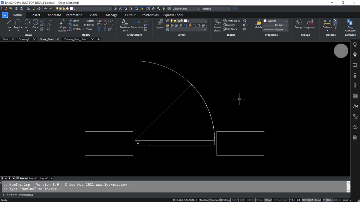
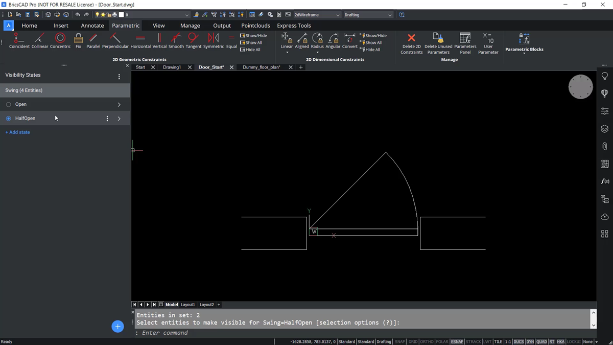
Working in a drafting workspace - for this example, the geometry contains the entities representing three distinct door configurations. These configurations are considered the different visibility states.
First, add visibility states to the door. From the ribbon, go to the parametric tab and to the far-right, and find the parametric blocks panel.
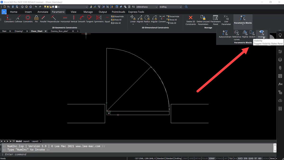
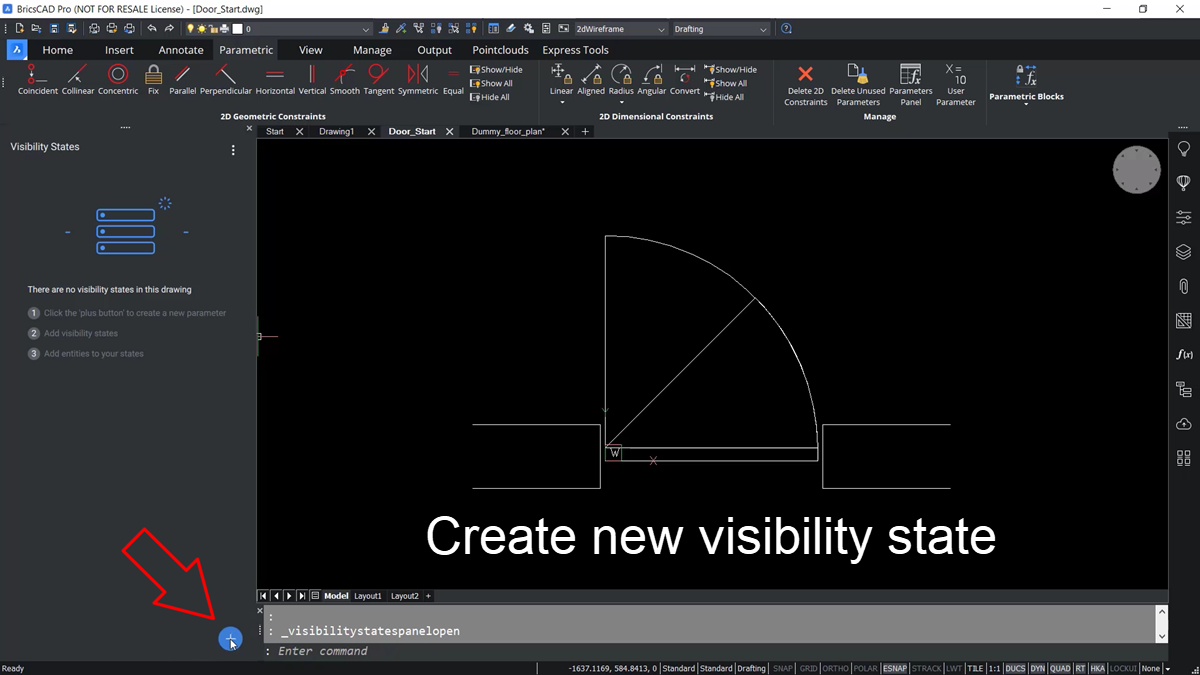
Select the visibility states panel. There are currently no visibility parameters defined - and no states present, because no parameters are currently defined.
To create a new visibility parameter, select the blue circle with a “plus in it” at the bottom right of the panel. It gives the visibility state parameter a default name. In this example, it is named “SWING.”
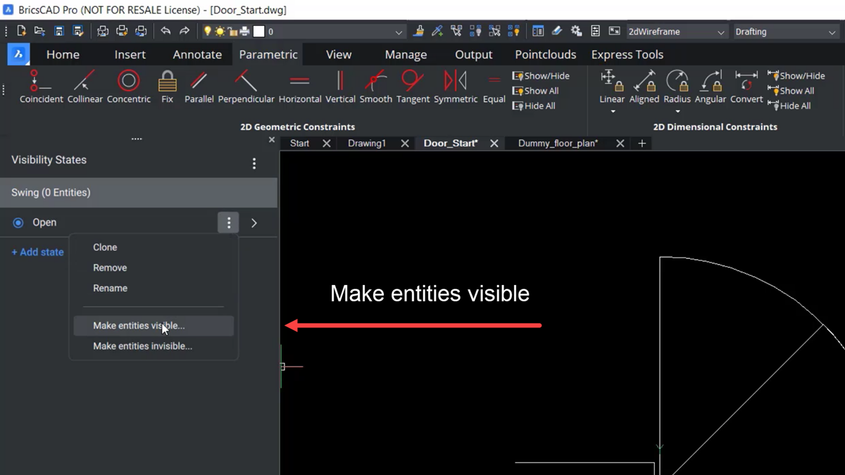
Define the different states or visibility options by selecting ADD STATE. Next, name the state for the open door – in this example, it is named OPEN.
Next to the OPEN property, when you hover over the panel, there are three dots representing a dropdown menu. Open the menus and choose the option to “make entities visible.”
Next, select the complete 90-degree Open Arc and the vertical line of the door. Together, these represent the full open door.
Those are the entities that you want to appear when the “OPEN - visibility state” is chosen.
Create another visibility state for when the door is half open, so select the ADD STATE again. This time, name it HALF OPEN.
Next, select Make Entities Visible select the 45-degree arc - representing a half-open door, and select enter, to complete the selection.
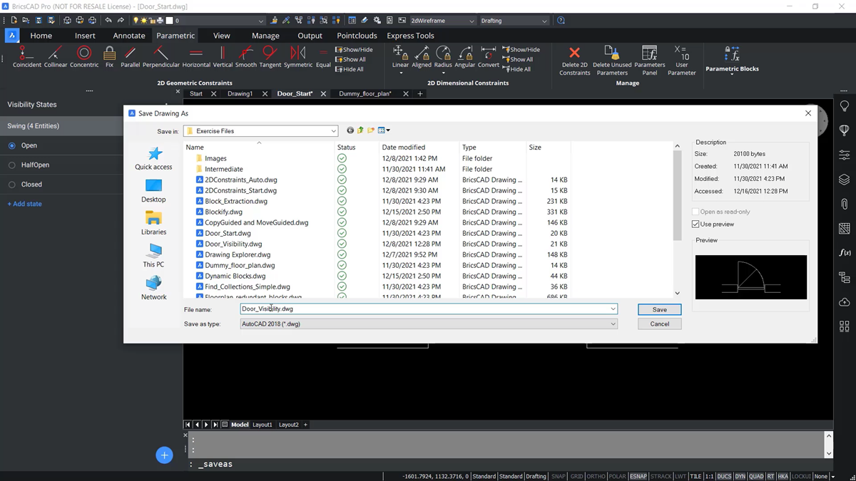
Finally, one more state to add - for a CLOSED DOOR. So, repeat the same steps as before and create a visibility state for a CLOSED DOOR. This time do not select any geometry in the CAD blocks because the rectangular door panel should appear in ALL states. Once finished editing the block, be sure to save it with a different name.
This block can now be stored in the block library. There is a library that comes with every license of BricsCAD. You can customize as you wish and add components like this door.
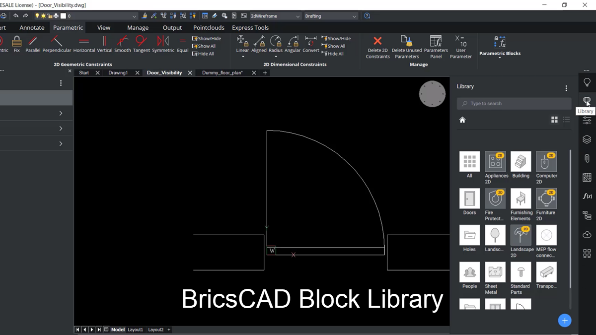
Notice there is a category in the Block Library for 3D doors, but currently, there is no category for any 2D Doors. So, the 2D Doors folder needs to be created.
To do this, go to the panels on the right, the library panel, and open it.
Open the library and select the blue button with the plus on it, in the bottom right-hand corner. When a new object is added to the library, it will also create a new folder for it simultaneously.
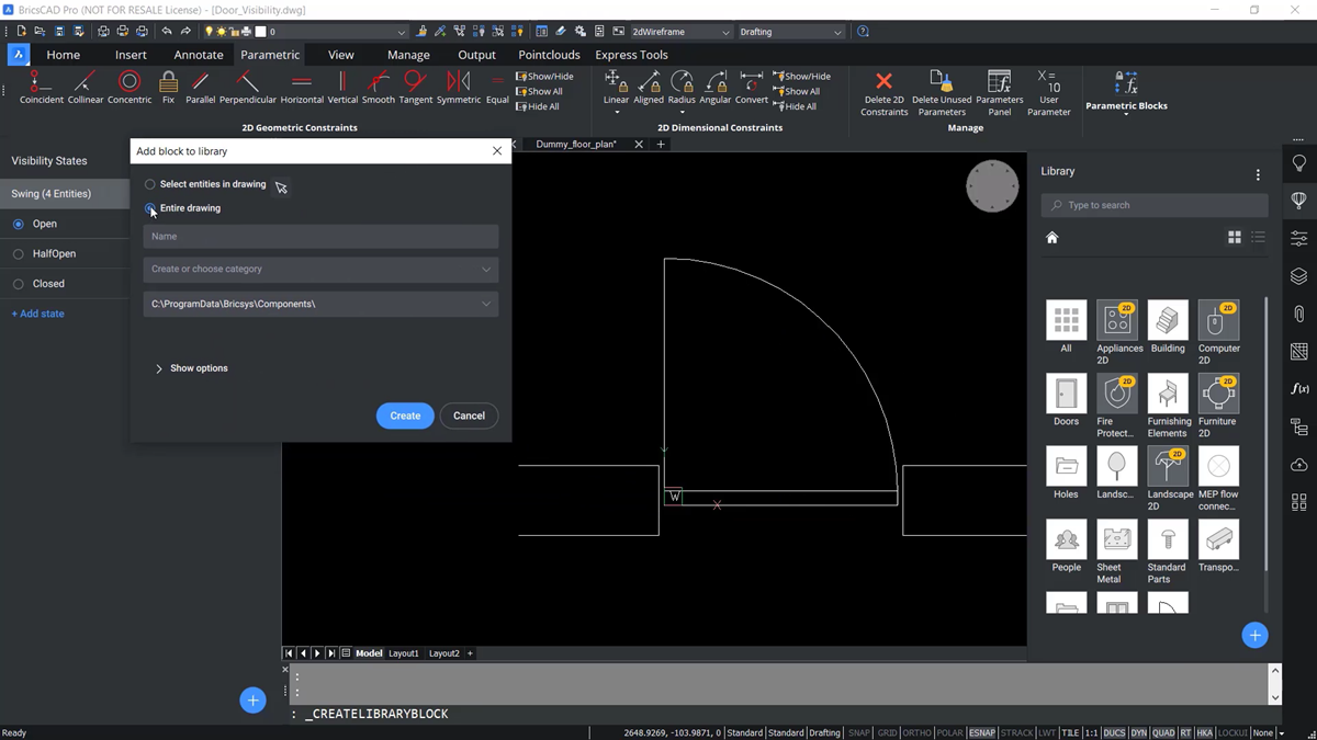
When the dialog appears, select the entire drawing. As a good practice, give it the same name as when it was first saved to keep things organized.
Once created, you can either create or choose a category. When you start typing in the door, BricsCAD tries to match it to one of the pre-existing categories.
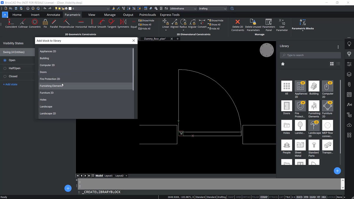
To override this, pick outside of that list, continue to edit, and call it Door 2D.
This folder doesn't exist, so it will be created on the fly. Generally, you do want it to be created it in the same components folder as the remaining library components - so select the create button. The new folder now appears in the block library.
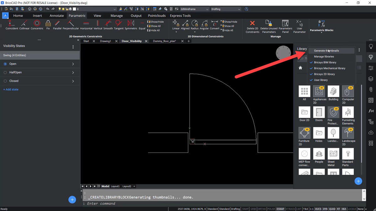
It is often a good idea to go to the menu at the top of the library panel and select the generate thumbnails command. This helps ensure that it has created a representation of this new door - in that door 2D folder.
You should see the door visibility file when you open the Door 2D category. Now, you can select this door visibility block, and place it in the drawing.
 See how much you can save by switching from AutoCAD to BricsCAD [ calculator ]
Adding Reference Curves to Parametric Blocks
An insertion point is not specified to help position the new block in the drawing. So, a scale factor for XY and rotation must be given to place the block. Ultimately, this is not the best workflow, so the saved version in the library needs to be edited.
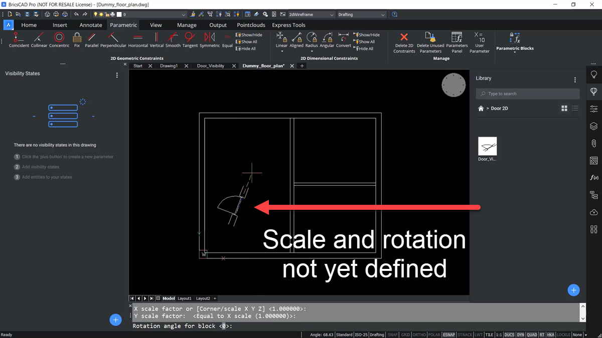
Reference curves need to be added to this block so it can more easily be inserted into the linework of the walls with this floorplan.
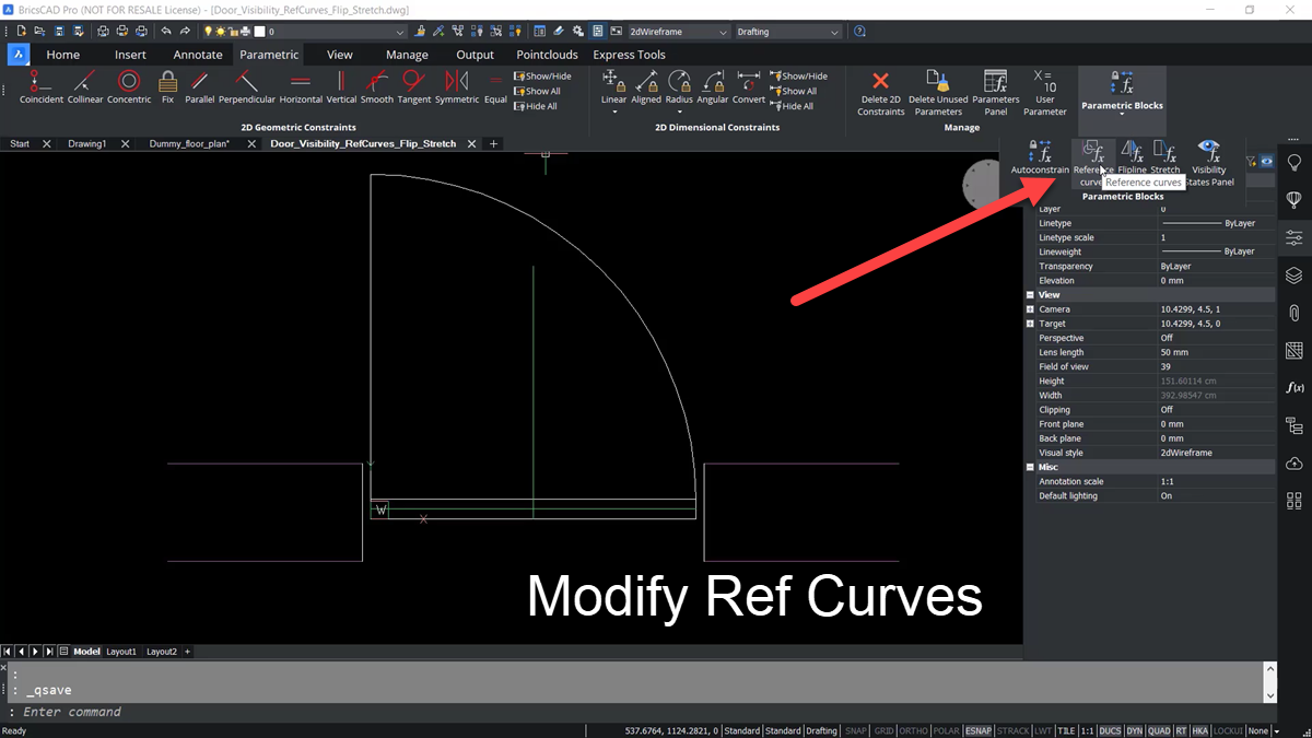
Go back to the parametric tab, go to the parametric blocks tab, and pick the reference curves tool. Next, select the four horizontal lines representing the block's wall. Notice that the lines have changed color.
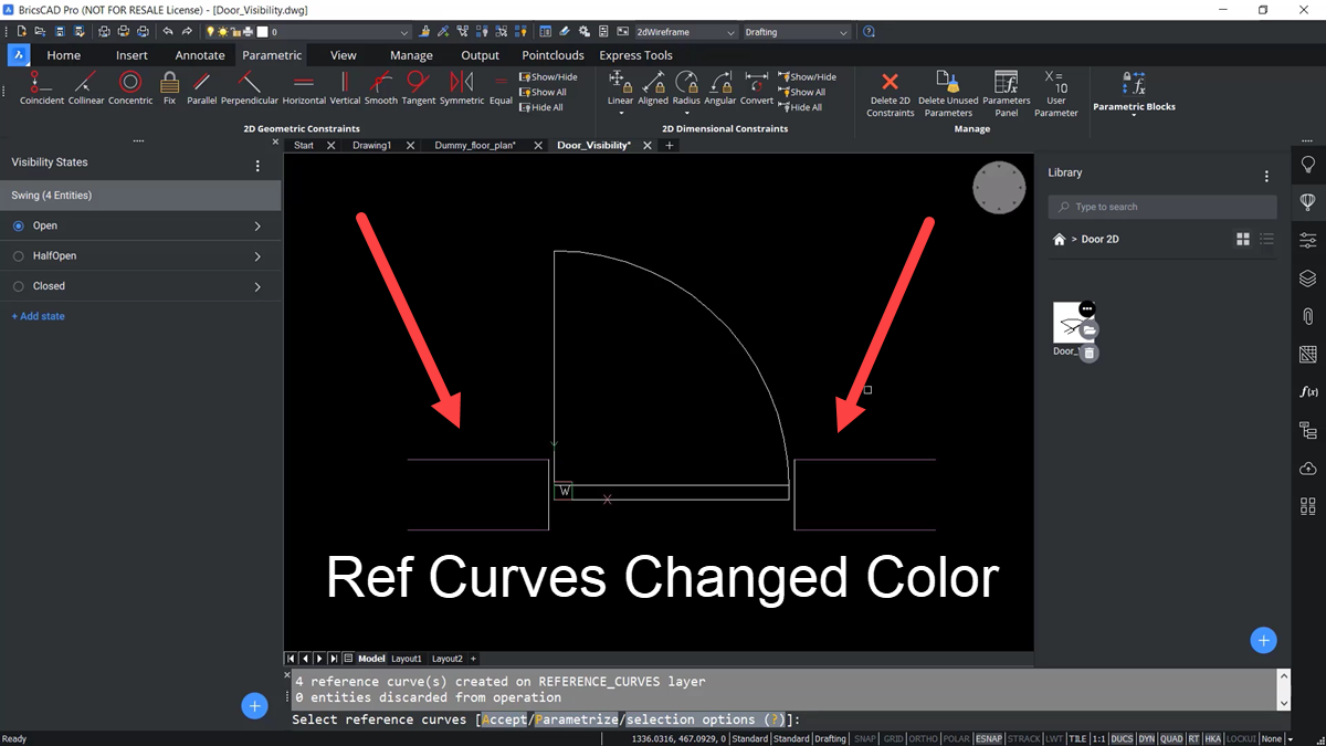
Going to the layers panel, there is a new layer called reference curves. Be sure to save this new block definition. Remember to refresh the thumbnails because it doesn't automatically do it for us.
Notice that in the new version, the door visibility block appears with a circle with an FX symbol, meaning it is parametric.
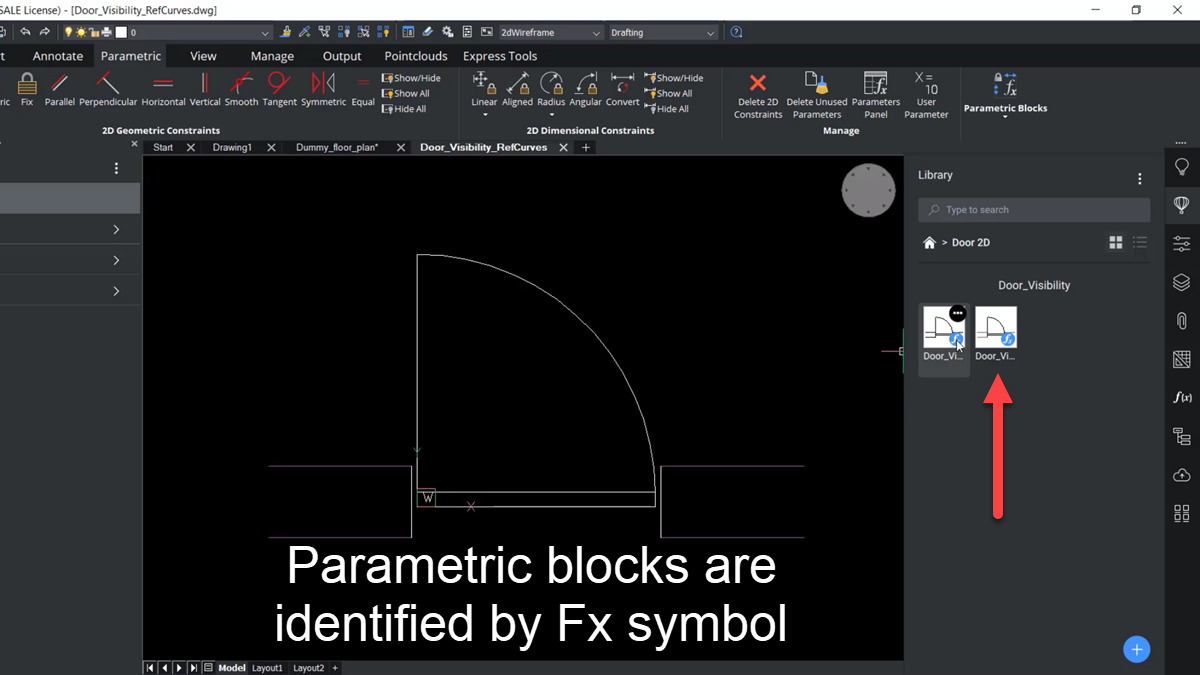
It doesn't specify what per perimetric functions it has, but it does identify it as a parametric block.
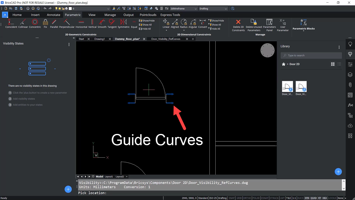
Going back to the floor plan, select the door visibility block. When it is moved into the drawing, notice that instead of showing the white lines, it's showing guide curves like those seen with the BricsCAD Copy Guided and Move Guided tools.
When the block is moved over the walls on the interior of the building, it does not match the width – but when moved over the exterior walls, it does.
Further Modifying Behavior of Parametric Blocks
This is where the power of BricsCAD’s parametric properties becomes evident. The door block can be modified so that once it is placed, you can change actions like which side the door is swinging from or whether it is swinging inside or outside the building.
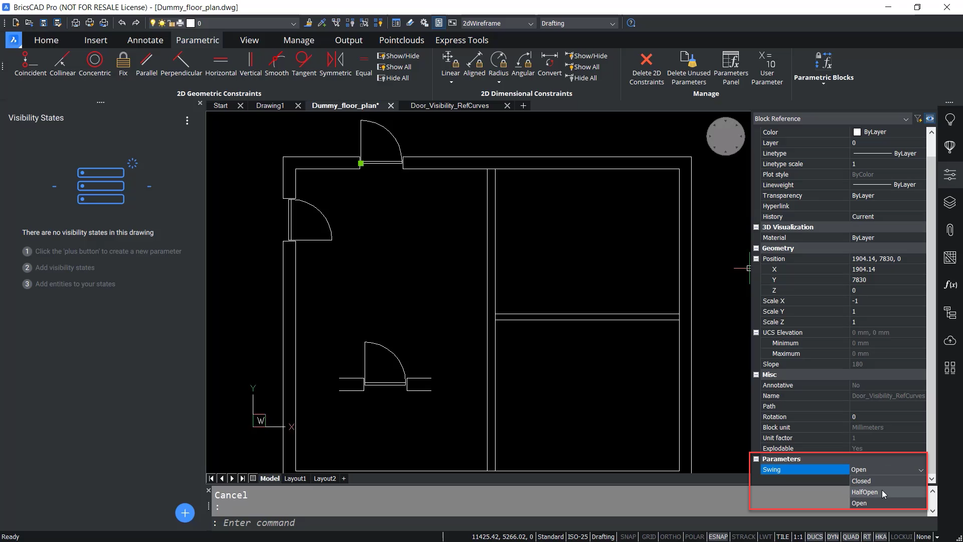
Right now, only the swing option is available, which allows you to change it to half-open or closed. We now want to add flip lines to this block.
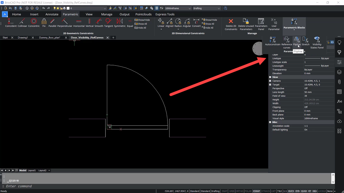
Open the block file again. Go to the parametric tab on the ribbon -- parametric blocks – flip line. Now, to create two flip lines. The first one will be a flip line, representing the hinge side of the door.
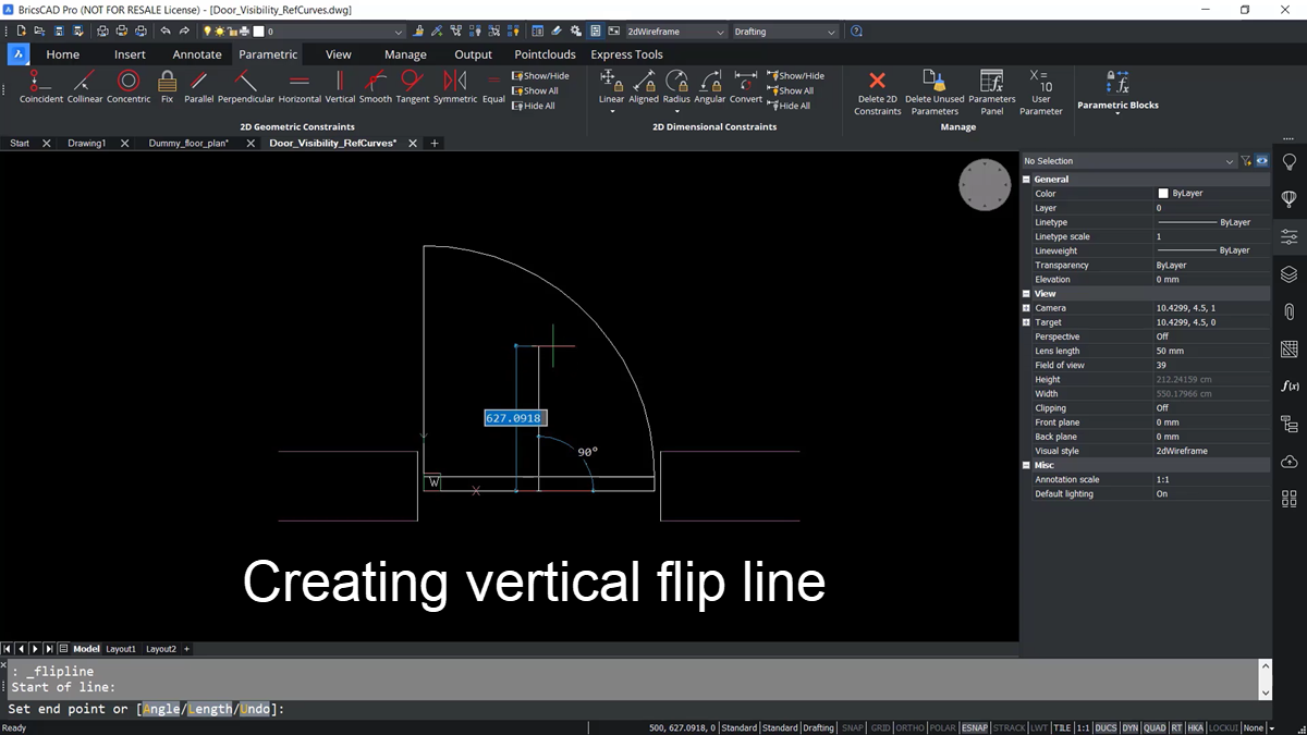
Snap to the midpoint of this door panel, then draw a line vertically – holding the shift key to ensure it is perfectly vertical. When prompted, name the flip line. In this example, it is called the hinge side.
To confirm the new flip line, go to the layers panel. we can see a new flip line layer; when we turn the display off, that green line goes off.
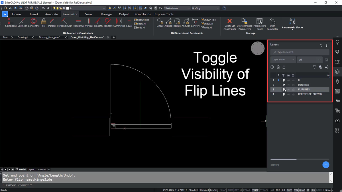
BricsCAD automatically categorizes items when using these tools and creates the needed layers. Now, it’s time to create the other flip line.
Following the same steps as before, create a horizontal line. In this case, this second flip line is called the wall side. There are two flip lines so the block can flip in two directions. Don’t forget to generate thumbnails again in the Library Panel.
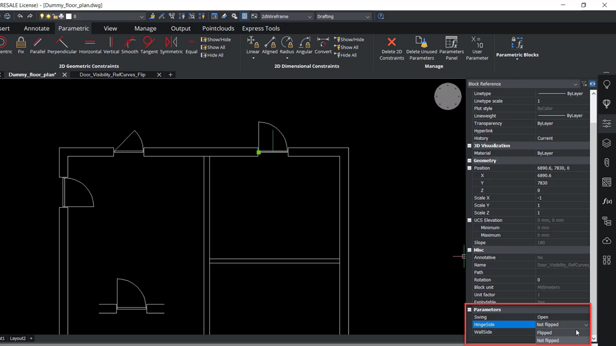
Place this block again in the drawing and see how it snaps to the outside walls. Also, if you go to its properties, it has two new parameters: hinge side and flip side. So now, you can switch it by just changing it from not-flip to flip.
Adding Stretch Geometry to the Block
To get even more functionality, you can add the ability to stretch some of the geometry. The stretch parameter works like the stretch command. It can be helpful when many entities are stretched or moved in the same direction, over the same distance, without editing the block.
In this case, the stretch parameter can replace several constraints to help simplify the drawing and the process of parameterizing the geometry.
Zoom into the door panel in the latest save block DWG, and go back to the parametric tab on the ribbon -- select parametric blocks, and this time, we will select stretch.
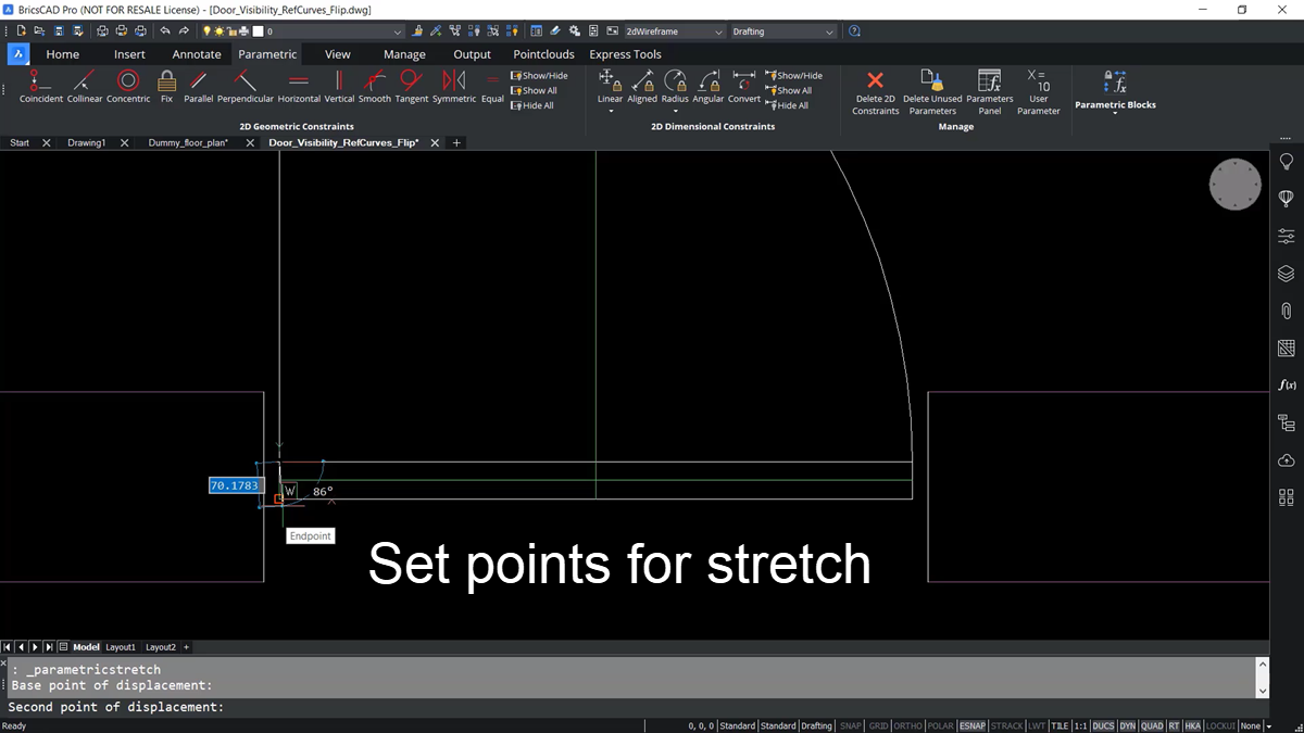
The Stretch Command asks to define a base point of displacement and a second point that defines the direction. Then BricsCAD asks (In the command line) to construct a stretch frame - a rectangle, that will go around the geometry to be edited.
Place the box representing the stretch frame around the geometry -- effectively defining what it wants to grab and stretch with this box.
For this example, the stretch frame is named thickness. Going to the layers panel again, you can see a parametric stretch layer.
In the floor plan file, if you place the block, you can see the line representing the stretch vector.
You can see a new thickness parameter if you go to its properties and go down to parameters. From here, you can enter a new value into the properties field to change the thickness of the door panel.
Create Flexible Guide Curves with Auto-constraints
The last thing to do is give the guide curves a flexible attribute to snap into walls of varying thicknesses. There is a new parametric feature that allows us to add what's called a fuzzy or flexible nature to the reference curves.
Return to the parametric tab, on the ribbon, and to the parametric blocks panel, and pick reference curves again. Then, at the command line, hit P for parameterize.
Next, use the coincident geometric constraint and selected the A for Auto-constrain option from the command line.
From there, pick a window around the intersection of the bottom-left horizontal reference curve and the vertical line representing the door opening. Doing this automatically applies a coincident constraint to those lines. Do the same thing for the other three corners of the guide curves.
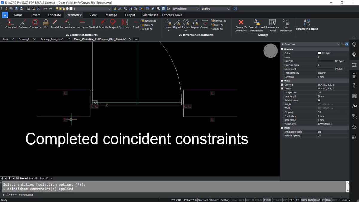
Once done, there are coincident relationships between the door opening's horizontal and vertical lines. In the properties, we can see some new constraints for offset and angle if you go to the parameter and constraints dialogue.
Right-clicking on one of these offsets and selecting animate, you can see that the reference curve and the end point of the door open move together.
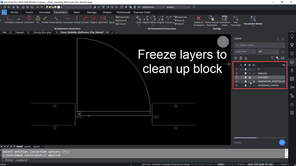
Cleaning Up the Block
To clean up the appearance of the block, freeze the flip lines, the parametric stretch, the reference curves, and go ahead and hide the geometric constraints.
Now if you grab the latest saved block and bring it into the floorplan drawing, Notice that it will snap to the outside walls, and now, it also snaps to the inside walls.
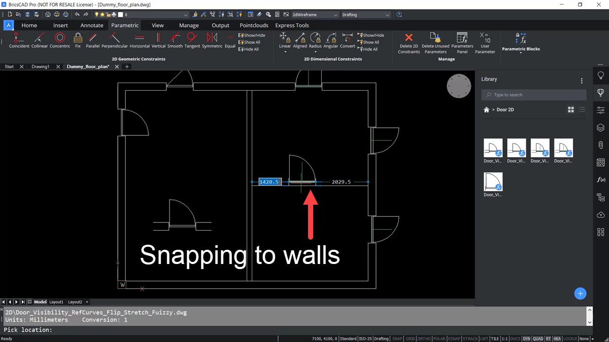
And the flip and the stretch parameters can still be adjusted too.
The result is a block for a very parametric door with a lot of functionality.
Conclusion
There is a lot of functionality available with Parametric Blocks in BricsCAD. You can create different visibility states and add them to your Block Library. From there, you can add guide curves and constraints so they snap into the geometry of your floorplans.
However, you don’t need to start from scratch. BricsCAD is fully compatible with AutoCAD block libraries and block references with AutoCAD blocks, including any Dynamic Blocks. You can migrate all those existing AutoCAD customizations into BricsCAD.
Are you interested in learning more? The best way to get started is to download the free 30-day trial of BricsCAD and test it for yourself. Try it, and you’ll quickly become a fan of BricsCAD.
What CAD Software is your choice for creating and editing blocks? Leave your answer in the comments.
You Can Count on TAVCO
In the complex landscape of AEC, you need a vendor as committed to quality and reliability as you are. TAVCO brings you just that—with high-performance tools like our durable large-format plotters, cutting-edge 3D scanners, and innovative software solutions.
We build long-term relationships fortified by unwavering support and innovative solutions that keep you ahead of the curve. Plus, when you have questions or need advice—including cost-effective options—you can always speak directly with a live TAVCO specialist, not a bot or an automated attendant

Comments